Easy guide to hardfacing: part 2
In the second part of our series on hardfacing, ESAB’s Mick Andrews walks Andrew Pearce through gouging.
In part 1 we covered a lot of ground – rod selection, buffering layers, pre-heating and cooling, welding technique, the set’s open-circuit voltage (OCV) requirement, and safety. All that’s left is how and when to weave while laying down hardfacing metal, then we can move to a different job: gouging and piercing.
There is only one rule concerning hardfacing weave patterns, and that is, there are no rules. How (and when) you do it depends on the wear that you’re trying to repair or to stave off and how much money you like to spend on electrodes.
The more and wider you weave the more heat toes into the work; the more diluted the expensive hardfacing metal becomes, and the more likely you are to end up with slag trapped in the deposit.
Mega-heat input is never a good thing when welding, producing extra distortion and often a greater chance of weld failure thought cracking, particularly in the heat-affected zone alongside the bead(s). High-heat input from over-enthusiastic weaving is also bad news when hardfacing high manganese steels (see Part 1) or brittle cast iron.
Some surfacing metal dilution is inevitable, and can even work in your favour when laying softer material on high-alloy steels. But normally, the hardfacing layer is thinned by the softer base metal that you are trying to protect, so in general you’ll need to put down two or maybe three layers of hardfacing to end up with the material’s full benefit. Either way, proper current selection and minimum weave is a priority.
The rule of thumb when weaving is simple: go no wider than 3x the electrode’s core wire diameter. That is 10mm tops for a 3.2mm rod, and so on. Because of hardfacing rods’ high recovery rate (see Part 1) you can cover a lot of ground with a relatively narrow weave pattern, so the restriction isn’t so bad.
Although there are as many patterns as people laying them down, a few principles will see you right. It makes sense to fully protect the leading edge of a soil-engaging part, usually with overlapping runs (1)*.
Side faces of thick items are often best tackled by laying down parallel beads, one along each edge, then filling the gap between them with a simple side-side weave (2).
Depending on rod diameter, sides can also be covered by a side-side weave alone (3); in both cases the rod’s fast-freezing deposit helps preserve the shape of the edge.
During the weave, pause briefly at the end of each sideways movement to let the crater fill. If the build-up in the centre of the weave is too heavy, either travel faster across that section or move a little further forward each time.
Away from tips and sides, exactly where you put the hardfacing is set by the likely wear pattern. A Worn part is the best guide here, showing the areas where pressure from soil of metal-to-metal engagement scallops away the steel.
When facing new parts, it is not always necessary to deposit great swathes of hardfacing. Instead, a criss-cross pattern (or even many large dots) creates a grid that fills with soil (4). Earth then flows over this so it cannot reach the soft base metal below. Bucket vertical sides and chisel plough points are good recipients of criss-cross weaving.
How do you cut grooves or holes, V-prepare joints or slice away old metal and rusted parts without a grinder or gas cutter? With a gouging/piercing electrode.
ESAB lists only one – OK 21.03 – so rod choice is as simple as the technique.
As the rod’s coating burns it develops a very strong gas jet and this blows away metal melted by arc heat. OK 21.03 works with steel, stainless steel, cast iron and most other metals apart from pure copper, and is particularly good for weld preparation in cast iron; arc heat dries out and burns off graphite and contaminants that would otherwise increase cracking risk.
It is also handy for opening a groove on the reverse side of a welded joint, before laying in a sealing run.
There are a couple of mini-snags. OK 21.03 needs 70 OCV minimum, so it cannot be used with most small, air-cooled sets. When cutting and piercing it prefers to be run DC+ (with the electrode holder plugged into the positive line); so if the farm has only an AC set you won’t get the best from it.
The grooves and holes you make won’t be millimetre-precise, and by its very nature, a gouging electrode can never be used to join material.
Technique
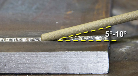
A gouging rod is used like a saw. To open a groove, strike the arc with the rod vertical to the work then quickly lay it down, ending up almost parallel to the surface – an angle of 5 degrees to 10 degrees is good (5). As the jet starts to open a trough, work it forwards and back as if you were cutting with a hacksaw.
The gouged channel will show a series of ripples corresponding to your sawing, like sand on a beach when the tide has gone out (6). To cut a deep groove make one run, clear any slag, then repeat as necessary.
Stick to rod pack suggestions for current. When this is right, the gouged channel will be largely clean and any slag will chip away easily (6). If the cut will not clear and fills up with foamy clinging slag, try more amps.
If it’s blasted into a wide channel and fills with tenacious slag, reduce current. Fig (7) has unpleasant examples.
Gouging can be done on the flat, vertically (start at the top and work down) or horizontally. Overhead works is best avoided or left to owners of a thoroughly fireproof hat.
Quick’n’ dirty holes can be chopped out or made bigger with a gouging rod. Although crude, the technique throws a lifeline to workshops without gas-cutting facilities.
Strike the arc with the rod vertical, then once the gas jet is established, saw the rod down through the plate (8). As with gas butting, the first stage until breakthrough is the hardest bit.
Once the arc is bellowing through the bottom of the plate, work round the edges to enlarge the embryo hole. Arc-pierced holes are not likely to win many beauty prizes, but the technique is a good way to make big openings in heavy sections when more sophisticated, neater methods are not around. It is also handy for rough-cutting away broken parts or seized fixings.
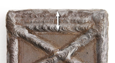
1. This slab of 25mm plate shows how hardfacing can be used. If it were a soil engaging part, the leading edge (arrow) would take most wear, so is faced with overlapping runs. A second layer would counter dilution.
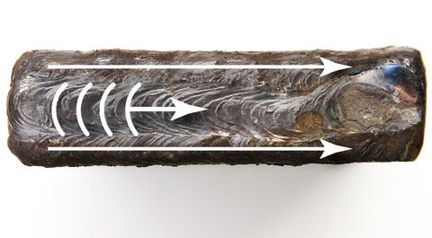
2. The long edges could be faced by two parallel runs (long arrows) filled by a compact weave.
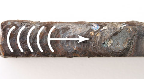
3. Or depending on electrode diameter and part thickness, by a single weave.
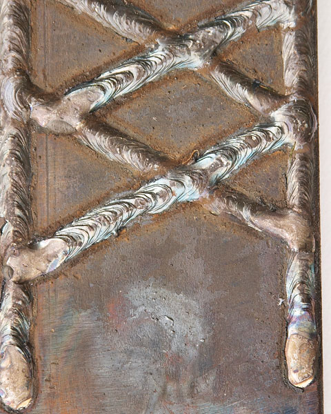
4. Away from maximum pressure points, a criss-cross weave holds soil to protect the underlying soft metal.

5. Strike a gouging rod vertically, then quickly lay it at a five degree-10 degree angle. As soon as the gas jet starts to dig, work the rod forwards and back like a saw.
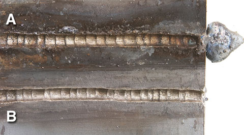
6. The rod pack suggests current setting and gives OCV requirement. When both are right there will be a little slag (A), which chips off easily to leave a clean, ripple-bottomed channel (B).
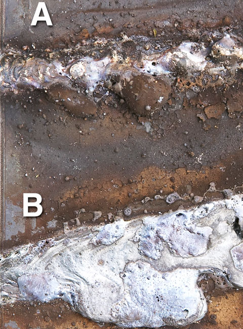
7. Too little current limits gas jet size, so it cannot clear tenacious slag (A). Too much current sees the gas jet overwhelmed by slag from the wide channel cut by arc heat (B). Either way it is a mess.
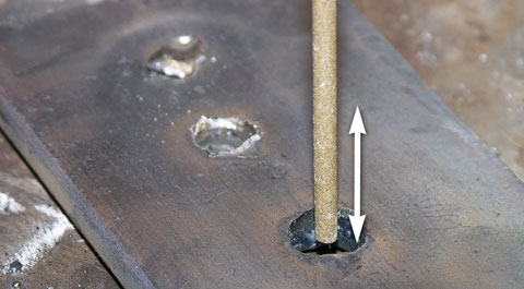 8. To pierce or enlarge a hole, strike the arc with the rod vertical. Saw it down through the plate (arrow) then round the edges.
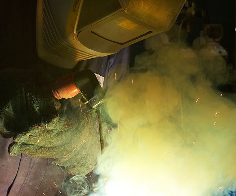
Gouging rods produce mighty clouds of fume. Extraction is the best answer, but failing that, wear respiratory protection and preferably work in an open doorway where the wind can help.
In the latter case, shield passers-by and livestock from eye-damaging arc light.
