Eleven steps to improve your MIG welding
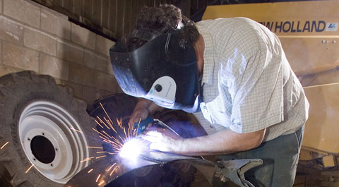
New to MIG? Andrew Pearce offers some suggestions to help the job along.
MIG’s ease of use makes it a favourite in plenty of farm workshops, but like many simple things there’s a bit more to it than meets the eye.
If you’re making the transition from stick welding, MIG turns many things around: you generally push the torch rather than pull it, there’s no flux to help beat contamination, you adjust voltage directly at the set then vary current through wire speed, and so on.
If you’re new to MIG, twiddling the various knobs to get a good result can tax the brain. Luckily there are beacons along the way, the most important of which are pictured here.
Depending on its capacity, a MIG set can offer three methods to get filler metal into the weld pool. Moving between the options — dip transfer, globular transfer and spray transfer — is down to adjustment.
Dip or short-circuit transfer is most common. It’s a low voltage, low heat process ideally suited to material up to about 6mm thick, usually involving 0.6mm-1.2mm filler wires.
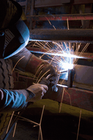 Heavier sections can be welded with vee preparation and multiple runs. Metal from the filler wire is placed directly into the weld pool between 20 and 200 times/sec, with a single drop left each time.
Dip transfer is a continuous cycle in which an arc exists until wire and pool meet; the resulting short-circuit pinches off a droplet and the arc re-starts. This busy, non-stop dip/short routine produces very little spatter and generates dip transfer’s characteristic fry-up sizzle.
Globular transfer sits between dip and spray transfers. As voltage rises, arc length grows and orderly dip transfer stops. Metal moves to the weld pool still occasionally by dip, but mainly by gravity as an ugly rain of gobbets.
Some of these hop out of the arc altogether, others smack into the liquid weld pool. Both produce heavy spatter.
Spray transfer happens at higher voltages still and so isn’t achievable on all sets. It’s a high-energy, hot process in which filler wire moves in an orderly way across the arc in a spray of fine droplets.
Spray transfer is grand for thick sections (where its heat provides potentially good penetration and fusion) but can’t be used for vertical or overhead work.
To move into spray mode, first set a high voltage and fast wire speed; then reduce wire speed until the arc stops crackling and starts to hum. The arc will lengthen, the weld pool widens and get much hotter, and arc light will jump up. Be prepared with thick gloves and a dark mask filter, shield the contact tip (see 11) and watch out for torch overheating.
1. Before welding starts.
 |
 |
|---|---|
| A | B |
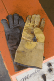
Thinner-leather TIG gloves (A) give a better feel for what’s going on than conventional welder’s mitts, and are fine for low voltage dip transfer. A variable-shade, self-darkening filter (B) lets you see what you’re doing, especially where arc light is limited. Whatever mask you use, do keep it clean — not like this one.
 2. Sort out the weld zone.
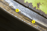
A MIG arc will sputter and the weld turn porous when it meets trapped soil (1), old arc weld slag (2), paint, grease or galvanising, for (unlike a stick electrode) MIG wire has no flux to carry off contaminants.
The shield gas can’t and won’t help, as it’s only there to stop gases in the air reacting with and weakening the forming weld. So this combine header skid will need grinding. If you can’t thoroughly clean the weld area, switch to stick welding and pray.
 3. Pick the right shield gas.
Argon plus 12-20% CO2 (and maybe 2% O2) is good choice for farming, delivering good penetration, relatively low spatter and a stable arc; it also tolerates minor plant mis-setting. A gas mix containing less than 18% CO2 will support spray transfer if your set can. Argon with 5% CO2 gives shallower penetration so is ideal for sheet work.
Pure CO2 is cheaper and give the highest penetration, but it can’t support dip transfer so the arc won’t run as smoothly, the weld finish will be rougher and there will also always be much more spatter. Only weld outdoors if you can rig up an effective shelter, as even a light breeze disturbs the gas shield.
4. Housekeeping 1:
 |
 |
|---|---|
| A | B |
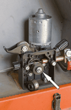
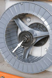
Look after the wire feed and spool. Now and again check that the feed rollers (A, arrow) are clean, oil-free and match the wire diameter in use. Set roller pressure and wire spool drag (B, arrow) so that with the torch trigger down and the feed rollers turning, you can just brake the moving wire to a stop with your fingers.
 5. Housekeeping 2:
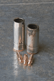
Contact tips and nozzles are disposable. The filler wire picks up welding current from the contact tip, and if the sliding connection between the two is not 100%, arc stability suffers.
Chuck out a tip when filler wire of the next size up goes through it. Ream out spatter inside the nozzle regularly, and reface the nozzle’s end as it erodes. Keep the torch’s gas supply holes clear, anti-spatter spray and debris will try to block them.
 6. Setup 1:
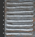
Adjust welding voltage first. Increasing voltage makes the arc progressively longer and wider so it heats a bigger area. Aim for a voltage which will give good penetration and fusion in the particular joint — look for a flattish bead, fused at the edges.
The welds above were made at fixed wire speed, increasing voltage each time. See how bead width grows with voltage from run 1 to run 8, and how spatter decreases? In 1 and 2, the small, low-energy arc can’t burn off wire arriving at the pool so the bead is humped, with spatter.
Through the middle band of good welding conditions (runs 3 to 5), voltage increased but arc energy and feed speed stayed in acceptable balance. By runs 6-8 the increasing high voltage can’t be satisfied by the volume of wire arriving, so the bead turns wide and very flat.
During the sequence noise moves from a harsh crackle to a smooth ripping, ending as a series of dismal pops.
 7. Setup 2:
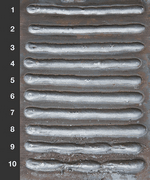
Adjust wire speed. Welding current rises with wire feed speed until the wire can carry no more, at which point extra speed just puts more filler into the joint.
The aim is to bring feed speed into balance with voltage, so filler wire is burnt off tidily and welding current matches the work. There’s no fixed point, just a band of good conditions inside which you can juggle wire speed to fine-tune current.
Aim for a flattish bead with good edge fusion. Runs 1-10 above show wire speed increased at a fixed voltage. For runs 1 and 2, speed was too slow and the weld pool was poorly filled.
Runs 3-6 fall in the good band. Runs 7-8 start to hump, showing that the wire is approaching its current-carrying capacity. By runs 9 and 10 unburnt wire stabbed into the work, juddering the torch. Arc noise moved from a whooshing pop, though a smooth ripping crackle to a popping rasp.
 8. Match current to material.
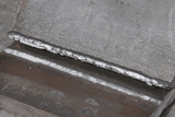
MIG can produce handsome beads even when voltage and wire speed are wrong for the job. This is a real problem when welding thick material with too little voltage and wire speed (wire speed = current).
Heavy plates quickly pull heat from the weld pool, so penetration and fusion suffer — the single pass T-fillet joint above, made in 12mm plate, failed after a few taps with a hammer.
The solutions are to use a voltage/wire speed combo that produces a flat, fused bead; to V-prepare butt joints and, where necessary, to lay down multiple runs to build up weld depth.
In T-fillet joints, throat depth is weld thickness from its outer face to the point where the original plates meet. Throat depth should equal the joint’s thinnest plate.
So when joining 6mm plate to something thicker in a T-fillet joint, throat depth should be 6mm, and so on.
 9. Sort your speed.
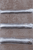
Work a little faster than you would when stick welding. From top to bottom, travel speed in the three runs above was too fast, about right and too slow.
When you tarry, the weld pool will tend to form on a ball of metal under the arc rather than on the area you’re trying to fuse, so aim to keep the arc up on the front edge of the pool.
Welding too slowly puts extra heat into the work, increasing distortion and risking burn-through in thin sheet.
 10. Manage stickout.
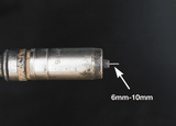
While you’re welding, wire beyond the contact tip becomes an electrical resistor. The higher you lift the torch the more wire there is between the tip and weld pool, so the higher is the resistance to current flow. As a result the arc is smaller, the weld pool cooler and fusion/penetration drop.
For normal work aim for 6mm-10mm stickout, bearing in mind that where the nozzle shrouds the tip you won’t see the true picture. Lengthen stickout a little to limit burn-through in thin sheet, otherwise keep it consistent for even penetration/fusion. In spray transfer, lengthen stickout to 20mm-25mm.
11. Tune nozzle height.
 |
 |
|---|---|
| A | B |
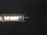
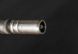
Some torches readily allow nozzle height adjustment, others can be persuaded into it by trimming back a nozzle at the business end.
For sheet work at low voltages, for corners and tight vees (or if you just want to see the contact tip to judge stickout accurately) set the nozzle so the contact tip pokes out (A). For higher voltages and spray transfer, shroud the tip with the nozzle to keep it cooler (B).

